English translation draft. Figures retain the Chinese labels in the supplied article; English captions are provided below. References are retained from the source and have not been independently reverified during this website conversion.
When interpreting eddy current signals, beginners often develop an intuitive rule: a larger flaw means more missing metal and therefore a larger signal amplitude.
That experience can be useful under certain conditions, but it is not a universal rule. A crack provides a simple counterexample: its opening may be very narrow and the volume of missing metal very small, yet it can produce a clear eddy current signal.
The key is that the instrument senses electromagnetic changes caused by a flaw; it does not measure flaw volume directly.
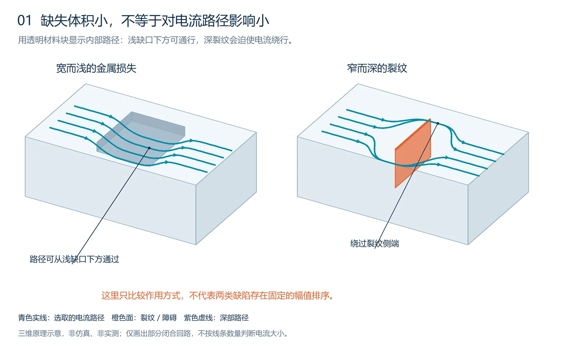
Figure 1. Conceptual illustration of eddy currents and a flaw, retained from the Chinese article.
1. How is the signal on the screen produced?
Alternating current in the probe coil produces an alternating magnetic field. When a conductive material is exposed to that field, closed-loop currents—eddy currents—are induced within it.
Those currents produce their own magnetic field, which acts back on the coil. The coil and material can be regarded as two coupled parts: each influences the other.
A flaw disturbs the original current paths and changes the current distribution. The reaction field, electromagnetic coupling, and losses also change.
For a self-inductance impedance probe, these changes appear as changes in coil resistance and reactance: ΔZ = ΔR + jΔX. With a separate receiving coil, they primarily appear as changes in induced voltage. The instrument converts these changes into the displayed signal. [1]
Between flaw geometry and signal amplitude lie two important steps: current redistribution and probe sensing. The second step can be understood intuitively by considering how two coils align.
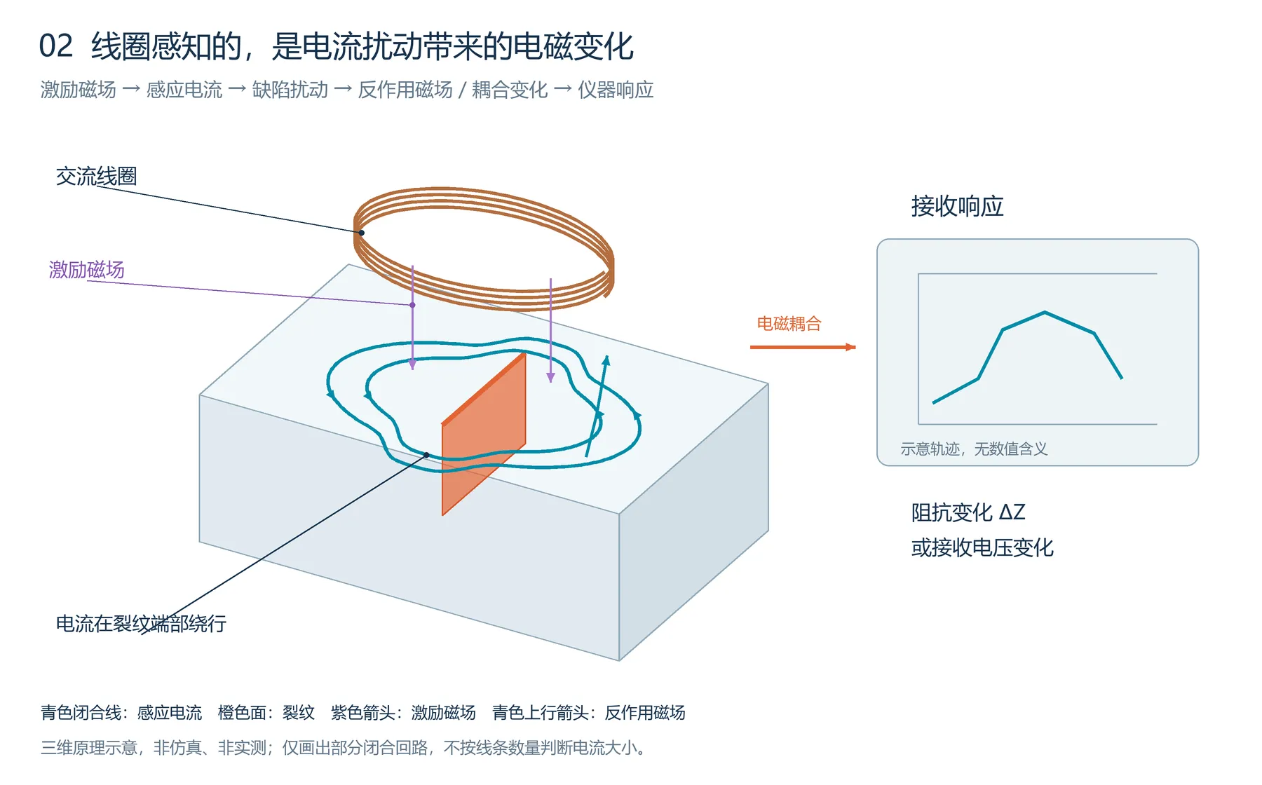
Figure 2. Conceptual eddy current and flaw illustration retained from the source article.
2. Why can a crack have a small volume but a large effect?
Imagine a narrow barrier across a road. The barrier occupies little ground, but if it crosses a main traffic route, vehicles must detour and traffic in the surrounding area is affected.
A crack can act similarly on eddy currents. When the crack face cuts across local current and electrical conduction between its faces is poor, current must flow around its ends, beneath its tip, or along other conductive paths.
The changed region is then larger than the small space occupied by the crack opening: current in the surrounding material is redistributed too.
A small missing volume does not imply a small change in current paths. Crack length, depth, and orientation may matter more than opening width in determining whether it forms a substantial barrier. Real cracks with face contact or metallic bridging may still conduct some current across the crack, changing the response.
It is therefore appropriate to say that a small crack can produce a large signal, not that crack signals are always large.
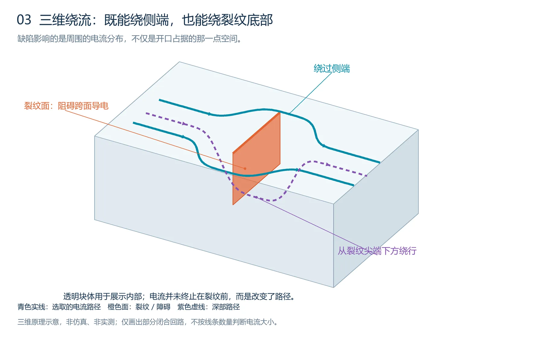
Figure 3. Conceptual illustration accompanying the discussion of crack-induced current redistribution.
3. Consider orientation and position before volume
The same crack generally causes a stronger disturbance when its face cuts across a main current path. If it lies approximately along the current, its obstruction may be much smaller.
This concerns the relationship between the crack face and the induced current direction. It cannot simply be replaced with the relationship between crack direction and scan direction; different probes produce different current distributions.
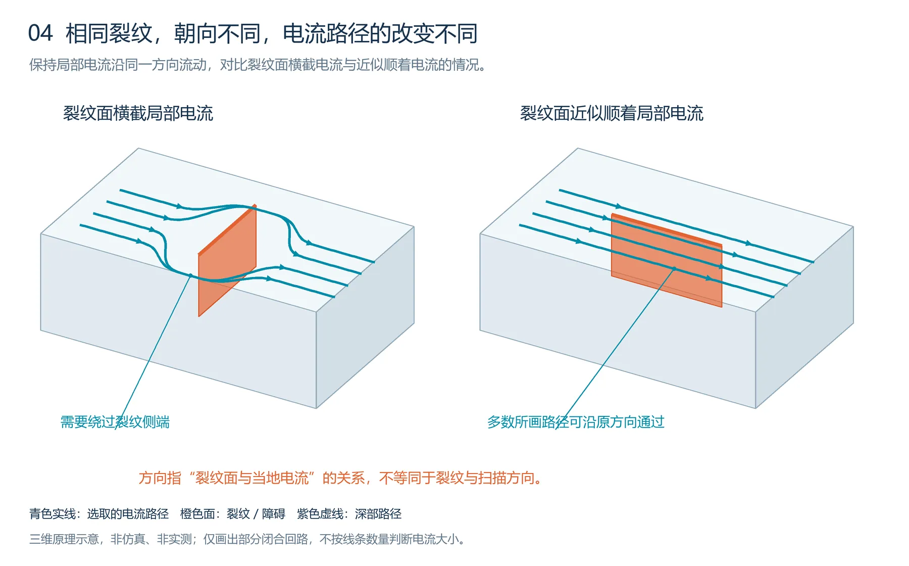
Figure 4. Conceptual illustration associated with flaw orientation and location; source figure labels remain in Chinese.
Position matters as well. Blocking a region of strong current differs from blocking a region of weak current. In common surface eddy current testing, current density generally decreases with depth, so otherwise identical flaws at different depths can produce markedly different responses. [1]
Even a substantial current change completes only the first step. The next question is whether the probe can sense that change effectively.
4. How should the receiving coil be positioned? Align the two loops
If the intervening magnetic field is difficult to visualize, think of a local eddy current loop as a second coil without a physical wire. Its interaction with the probe can be understood through mutual inductance between two coils. [3]
For an approximately planar, single dominant local loop, begin with parallel loop planes, aligned centers, and a small separation—like placing two circular rings one above the other.
“Sense the current loop with a coil whose plane has a similar orientation.”
The alignment concerns the planes of the two loops. It does not mean aligning the coil axis with one short segment of current. Knowing the direction of current along a small segment is insufficient to determine the best arrangement.
For flaw sensing, the rule needs an addition: align with the current loop affected by the flaw, and place the coil’s sensitive region over the location where current changes substantially.
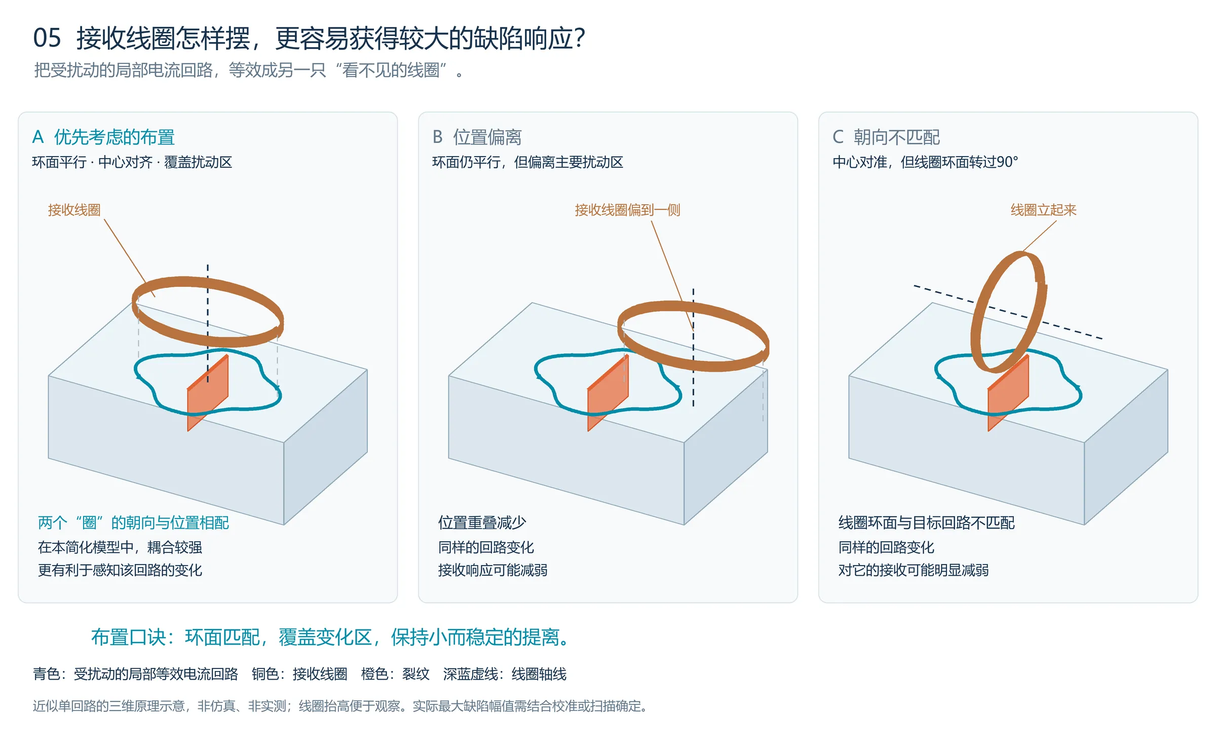
Figure 5. A has a suitable orientation and position; B is displaced from the main disturbed region; C is centered but its loop plane is rotated by 90°. For the illustrated single-loop model, A is more favorable for sensing the change.
A real flaw may disturb several loops whose responses add or cancel. What matters is the difference between the flawed and unflawed conditions: strong background coupling does not automatically mean maximum flaw amplitude. This rule is useful for intuition and initial arrangement; calibration or scanning is still needed to establish the final position.
In magnetic-flux terms, for a small air-core coil in the same approximately uniform alternating magnetic field, with other conditions equal, the received amplitude is greatest when its axis is parallel to the changing field; the ideal response is zero when the axis is perpendicular to that field. The axis is normal to the coil plane. [4]
5. How can we understand a “current-interception area”?
An analogy with ultrasonic testing can help: with other conditions similar, reflector orientation relative to the sound beam and effective reflecting area affect the echo.
For eddy currents, imagine local current as a flow. A flaw that more strongly obstructs the conducting paths normal to that local flow is more likely to create a substantial disturbance.
This analogy helps explain orientation but cannot directly calculate amplitude. Eddy currents form closed loops and divert around obstacles; reception also involves phase-dependent addition and cancellation.
The interception-area analogy helps explain how a flaw changes current; the aligned-loop analogy helps explain how a probe senses that change. Together, they describe the inspection process more closely than flaw volume alone.
6. Why does “larger volume, larger amplitude” often work in practice?
Within one flaw family, greater volume often comes with greater length, depth, or affected area. If material, orientation, location, probe, frequency, and other conditions remain similar, amplitude may increase accordingly.
For example, increasing the dimensions of similarly shaped artificial flaws usually affects more effective current paths. This does not justify grouping holes, slots, corrosion, and real cracks together and converting their missing volumes directly into amplitudes.
As a flaw becomes deeper or longer, the additional portion may lie in a region of weak current or low probe sensitivity, so the rate of amplitude growth can decrease.
Broad, gradually varying thinning may involve substantial metal loss while producing similar responses in two differential coils. Subtracting those responses can yield a small output. This is one reason to consider both absolute and differential channels in tube inspection. [2]
7. How should a large amplitude be interpreted?
First check whether the comparison conditions match: probe, frequency, gain, lift-off, channel, and whether the measured quantity is signal magnitude, one axis component, or a peak-to-peak value. Screen heights are not directly comparable when these conditions differ.
Then assess phase, waveform, spatial distribution, and suitable reference specimens. Amplitude is valuable, but amplitude alone does not establish flaw volume, maximum depth, or severity.
Ask three successive questions: How does the flaw obstruct current? Where does it obstruct it? Can the receiving coil match and cover the main region of change?
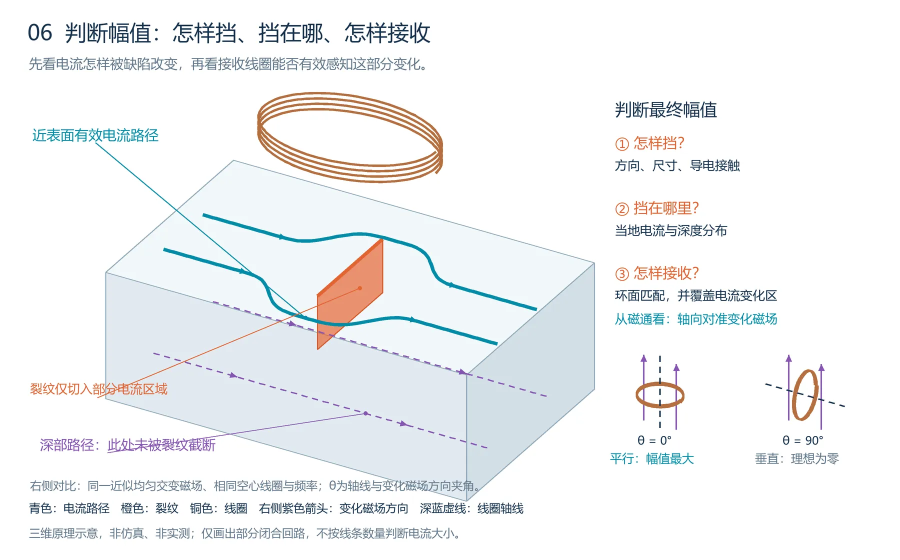
Figure 6. Source illustration accompanying the three questions for interpreting flaw amplitude.
Once these questions are clear, it becomes easier to understand why even a small crack can produce a large signal.
Eddy current amplitude can correlate with flaw volume, but it is first a result of the combined effects of the flaw, current distribution, and probe.
References retained from the Chinese article
[1] FHWA. Eddy Current Testing (ECT), InfoTechnology.
[2] IAEA. Eddy Current Testing at Level 2. Training Course Series No. 48, 2011.
[3] OpenStax. University Physics Volume 2, 14.1 Mutual Inductance.
[4] OpenStax. University Physics Volume 2, 13.1 Faraday’s Law.